




Rail-Guided Recessed Stage Lift


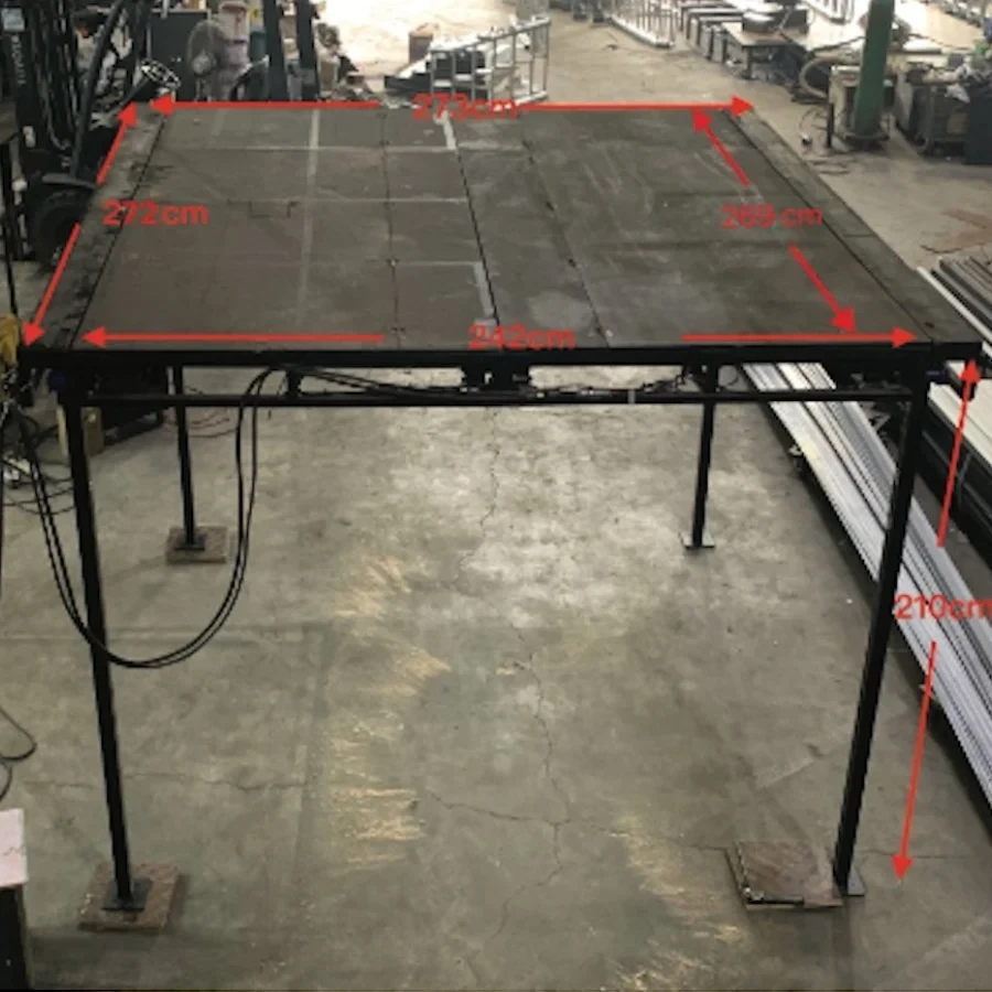
The gear rack-driven recessed stage lift is a lifting solution designed for installation inside a technical pit beneath the stage floor. It allows the lift platform to move from a lowered position below floor level to a position flush with the stage floor when required for performances. The preliminary design uses a geared motor with synchronized drive on both sides through a gear-and-rack mechanism, providing an approximate 2,000 mm lifting stroke and a WLL of 250 kg under uniformly distributed load. The system is suitable for performance stages, studios, multipurpose rooms, and other spaces where the lifting mechanism needs to remain concealed.
Scope and Intended Use
The proposed system is a recessed stage lift installed within a technical pit. When in the lowered position, the platform is located below the stage floor level. When fully raised, the platform is aligned flush with the stage floor, allowing props, equipment, or performers to be brought to the performance position.
-
Applications: Performance stages, studios, multipurpose rooms, and performance areas where the lifting mechanism needs to be concealed.
-
Operating mode: Operator-controlled raising/lowering. The system must not operate automatically when the operating area has not been secured.
-
WLL 250 kg: Defined as the useful load uniformly distributed across the platform, excluding the self-weight of the platform and moving mechanism.
Limitation: The system must not be used as a public passenger lift. If performers are to be lifted, an additional risk assessment, an independent fall-arrest system, and compliance with applicable regulations and standards are required.
Preliminary Technical Specifications
| Parameter | Preliminary Value | Status |
|---|---|---|
| Overall frame dimensions | 2,000 × 2,000 mm | As per drawing |
| Usable platform dimensions | Approx. 1,600 × 1,800 mm | As per drawing |
| Lifting stroke | 2,000 mm | As per drawing |
| Base assembly height | Approx. 240 mm | As per drawing |
| WLL | 250 kg, uniformly distributed load | As required |
| Speed | 10 m/min (0.167 m/s) | Assumed – to be confirmed |
| Travel time for 2 m | Approx. 12 seconds | Calculated from speed |
| Motor shown on drawing | 1 HP ≈ 0.75 kW | Requires verification |
| Main structure | 40 × 80 mm and 50 × 100 mm box sections | As per drawing |
| Drive system | Motor + gearbox + twin chain + gear/rack drive on both sides | As per drawing |
| Guidance system | Guide rollers at the corners | As per drawing |
| Power supply / duty rating | Not yet specified | To be defined |
Mechanical Construction
| Assembly | Function / Requirement |
|---|---|
| Fixed pit frame | Provides the guide rails, accommodates lateral loads, and connects to the stage structure. |
| Lift platform | Constructed from 50 × 100 mm box sections, supporting the finished surface and transferring loads to the drive assemblies on both sides. |
| Geared motor | Generates the lifting torque; an electromagnetic brake motor with variable frequency drive (VFD) is recommended. |
| Twin shaft / chain drive | Distributes motion synchronously to both sides to minimize platform tilting. |
| Gear and rack mechanism | Converts rotary motion into vertical linear motion. |
| Guide rollers | Restrict lateral movement, maintain the required clearances, and prevent jamming. |
| 100 × 150 × 10 mm mounting plate | Connects the rack to the frame; dimensions and welds must be verified for load-bearing capacity. |
Operating Principle
-
Command input: The PLC checks the E-stop, technical pit/door status, sensors, and brake condition.
-
Brake release and acceleration: The VFD controls motor acceleration according to a predefined ramp to minimize shock and vibration.
-
Torque transmission: The gearbox transfers torque to the twin shaft/chain drive, driving the gears on both sides.
-
Synchronized lifting/lowering: The gears engage with the racks while the guide rollers maintain the platform in a level position.
-
Deceleration and stopping: Position sensors initiate deceleration before reaching the floor level, while limit switches ensure accurate stopping at the operating limits.
-
Load holding: The motor brake engages, while an independent anti-fall mechanism provides protection in the event of a system failure.
-
1 Star
0
-
2 Star
0
-
3 Star
0
-
4 Star
0
-
5 Star
0
Filter by keyword
All
Reviews 5 ★
Reviews 4 ★
Reviews 3 ★
Reviews 2 ★
Reviews 1 ★





No reviews yet.