

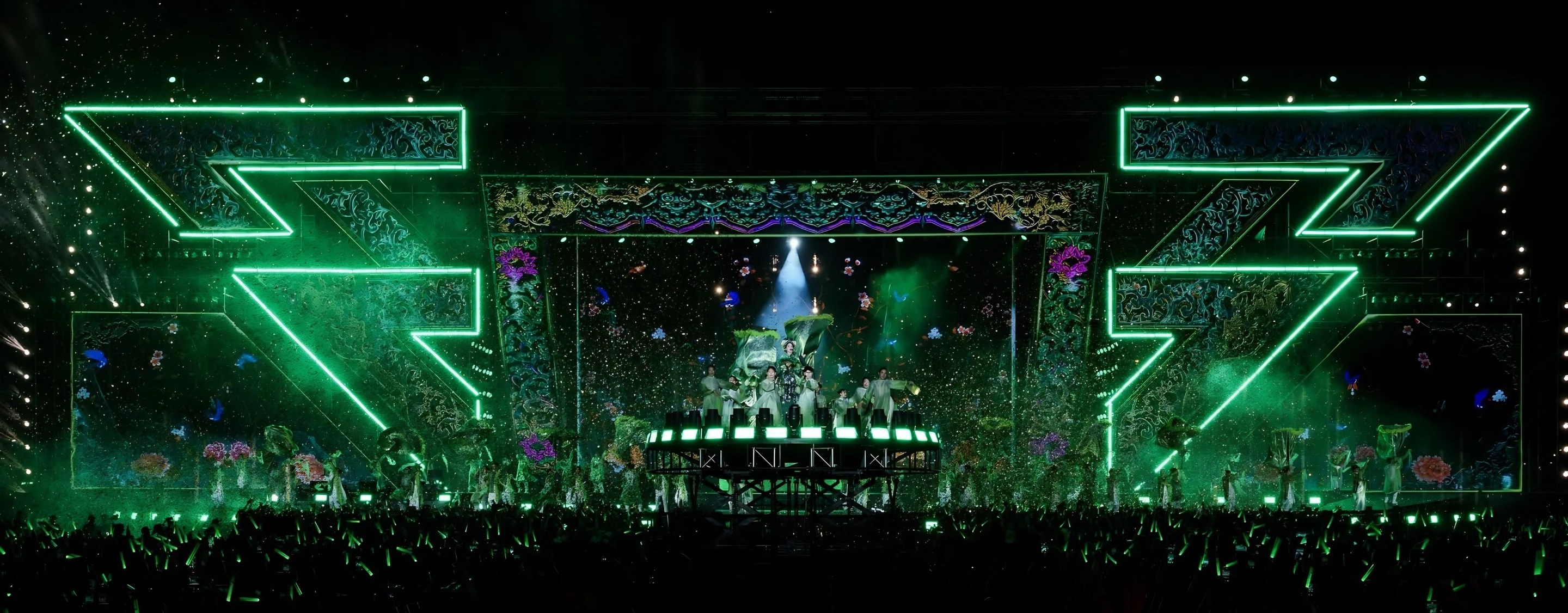
MPX STAGE EQUIPMENT & MOTION MECHANICAL SYSTEMS
MPX owns a comprehensive system of stage equipment and motion mechanical systems serving live concerts, performances, TV shows, festivals, and large-scale events. The equipment portfolio is organized by application groups, including synchronized hoists, programmable hoists, stage lifts, rotating stages, sliding rails, trusses, and load-bearing structures, meeting requirements for safety, system integration, and practical operation.
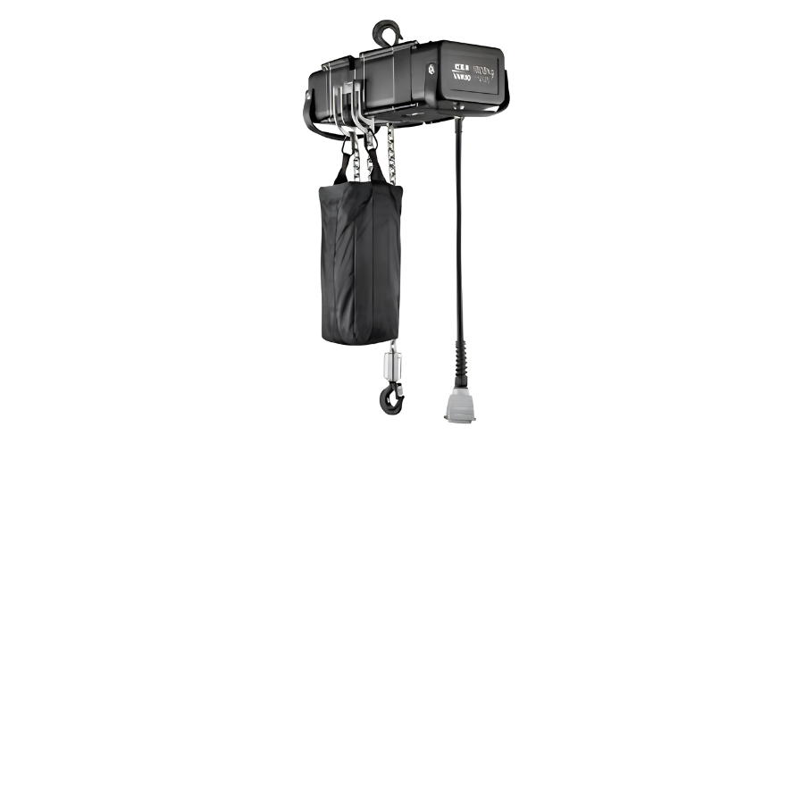
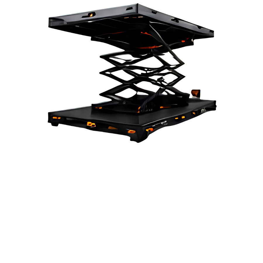
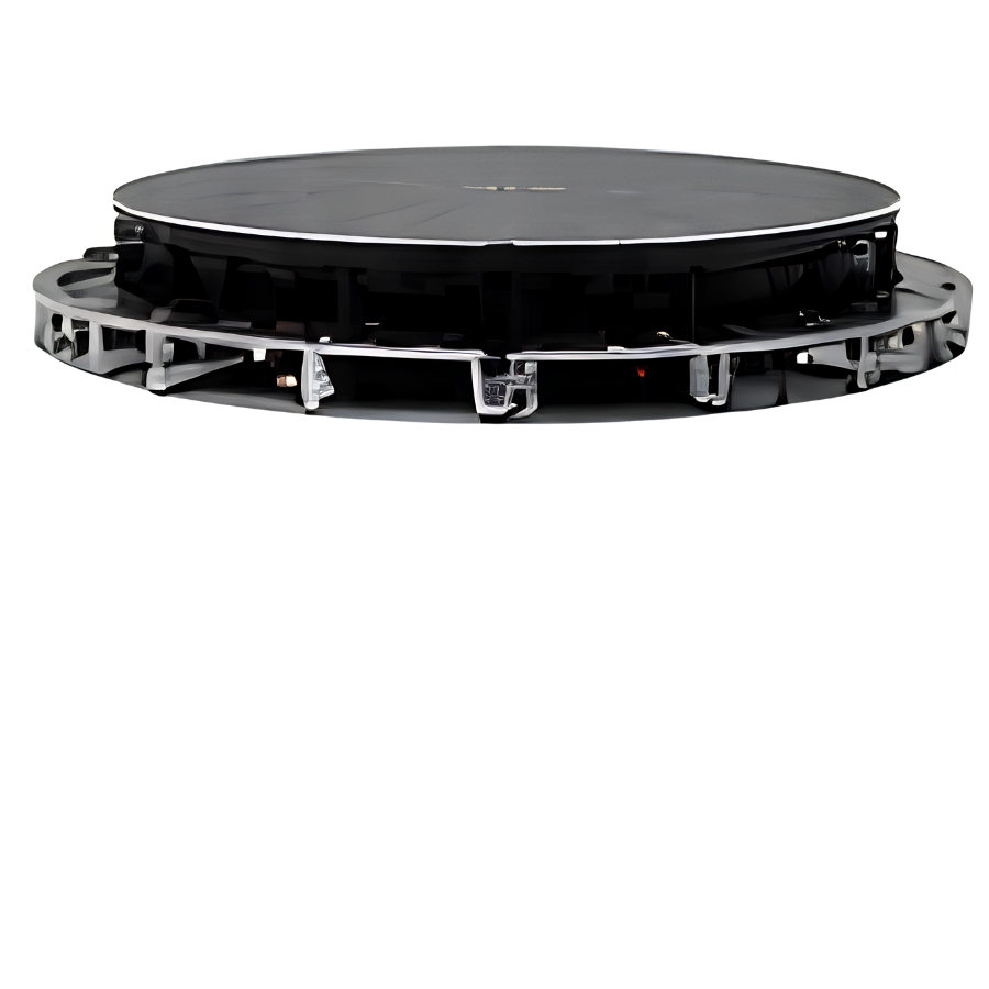
04. SLIDING RAILS & MOTION SYSTEMS
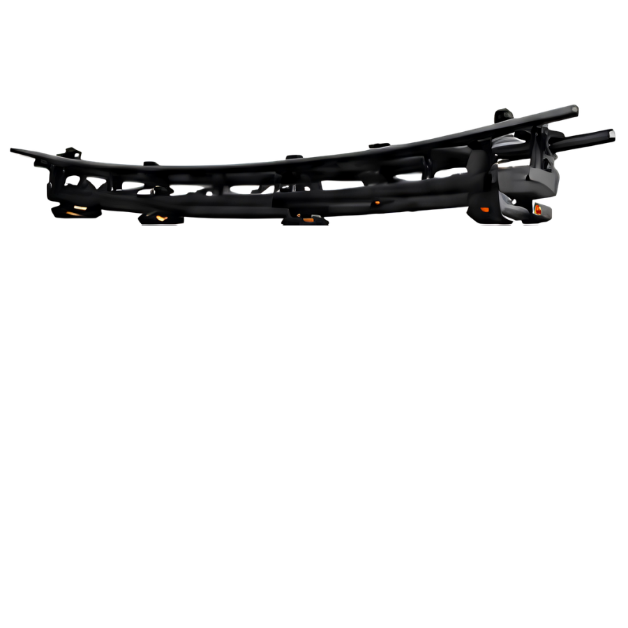
- • Suspended Sliding Rails
- • Heavy-Duty Sliding Rail Platforms
- • 360-Degree Rotating Motors
PRACTICAL APPLICATIONS
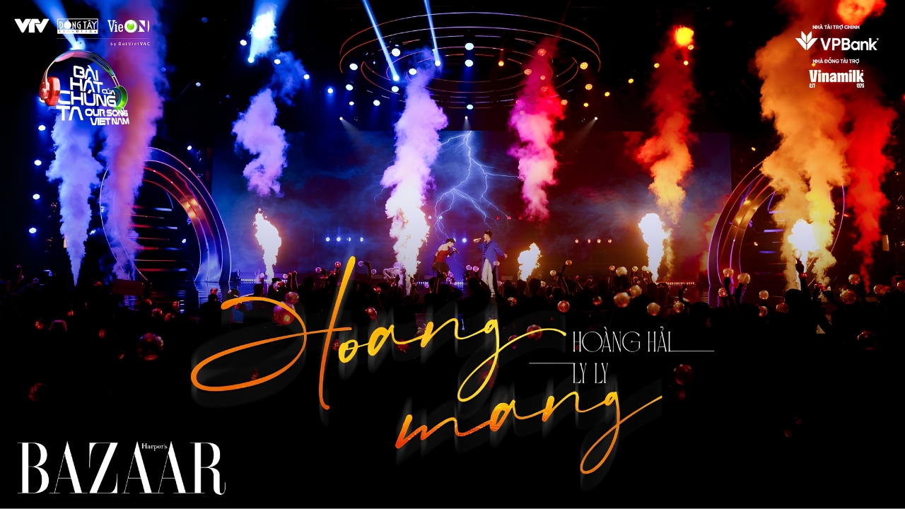
LIVE CONCERT
Live stages, concert tours
FESTIVAL
Music festivals, large-scale events
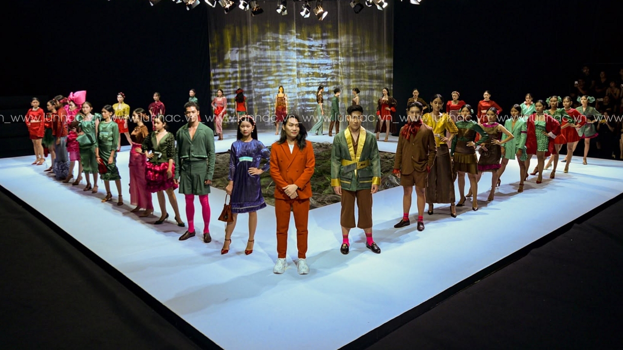

FASHION SHOW
Fashion shows
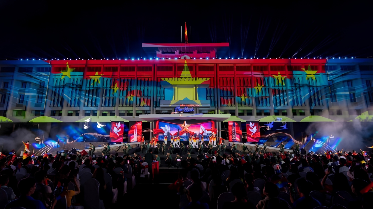

AWARD CEREMONY
Award ceremonies, recognition events
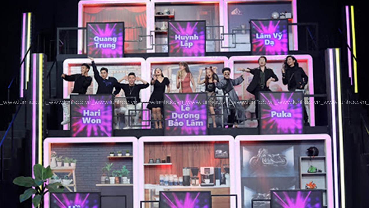

TV SHOW
Game shows, live television broadcasts
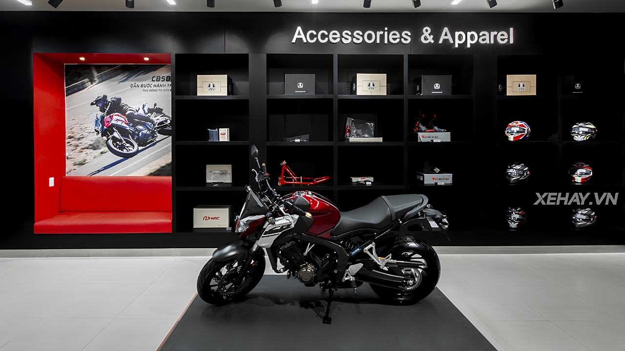

ACTIVATION
Brand activation, experiential events
Featured Equipment
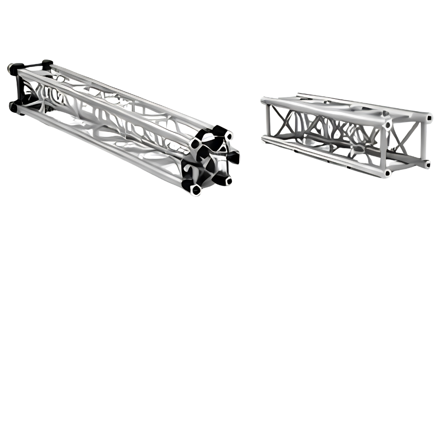
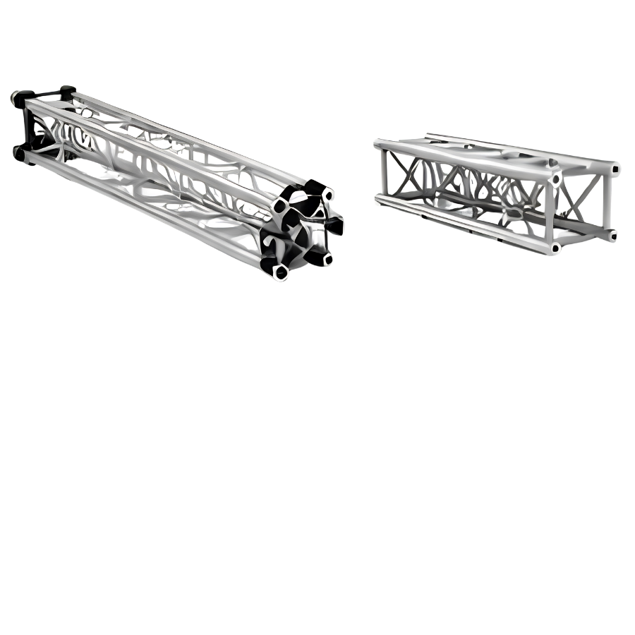
Steel Truss
Product Overview MILOS S-RTW 145 , also known as S-M1450 Rect , is a rectangular steel truss developed for stage structures requiring high load capacity and long spans. The system uses ultra-high-strength steel, features an approximately 1,450 × 770 mm cross-section, and can achieve a published span of up to 50 m under the manufacturer's specified design conditions. Compared with an equivalent-size aluminum truss, the S-RTW 145 provides approximately 2.2 times the load-bearing capacity while weighing only about twice as much. This makes it suitable for main grids, roof systems, PA wings, video wings, and other structures requiring long spans while minimizing the number of towers or intermediate support points. Key Advantages Very High Load-Bearing Capacity Its high-strength steel construction and deep cross-section provide high bending resistance, making the truss suitable for heavy LED, PA, lighting, and large-scale scenic loads. Long-Span Capability With a published span of up to 50 m, the S-RTW 145 can create wide stage spaces while reducing the number of support points required within performance and audience areas. Optimized Load-to-Weight Ratio The system provides approximately 2.2 times the load-bearing capacity of an equivalent aluminum truss while weighing approximately twice as much. Rigging and Logistics Features The truss incorporates forklift pick-up points, ladder tubes, and compression tubes at key locations to facilitate handling, rigging, and transportation. Stage-Ready Finish The truss features a matte black industrial coating designed to withstand impact while minimizing reflections during filming and live performances. Operational Value Allows multiple pieces of equipment to be concentrated on a controlled main grid. Enables long-span structures for festivals and outdoor concerts. Can reduce the need for multiple intermediate towers where permitted by the structural design. Suitable for long-term investment by companies specializing in roof systems and heavy-duty rigging. Technical Specifications Source: MILOS S-M1450 Rect datasheet and S-RTW 145 product page. Item Specification Manufacturer MILOS Truss System S-RTW 145 / S-M1450 Rect Structure Type Rectangular steel truss Cross-Section Dimensions 1,450–1,451 × 770–771 mm Main Chord A Ø101.6 × 4 mm Vertical Brace B Ø60.3 × 4 mm Vertical End Brace C Ø60.3 × 4 mm Horizontal Brace D Ø48.3 × 3.2 mm Horizontal End Brace E 80 × 60 × 4 mm Intermediate Horizontal Brace F Ø48.3 × 3.2 mm Connection Type Orientation-free double-fork connector Pin Type PW; galvanized pin Horizontal Connection Holes Ø22 mm at end brace Maximum Published Span 50 m Approx. Weight per 3 m Section 125–126 kg/m Finish Matte black, impact-resistant industrial coating Design Load Factors Self-weight: 1.35; imposed load: 1.5 Standard Lengths and Weights Length Weight 1.0 m 222.4 kg 2.0 m 288.6 kg 2.5 m 310.5 kg 3.0 m 375.3 kg 4.0 m 459.3 kg 5.0 m 526.5 kg 6.0 m 593.7 kg Weights exclude connection hardware and packaging. Reference Load Table The values below are taken from the MILOS loading chart. CPL refers to a concentrated load applied at mid-span, while UDL refers to a uniformly distributed load along the span. The self-weight of the truss is included in the table. Span Mid-Span CPL CPL Deflection UDL UDL Deflection 15 m 30,379 kg 47 mm 2,816 kg/m 41 mm 20 m 22,272 kg 85 mm 2,083 kg/m 98 mm 25 m 17,291 kg 134 mm 1,383 kg/m 164 mm 30 m 13,873 kg 195 mm 925 kg/m 236 mm 35 m 11,348 kg 269 mm 648 kg/m 323 mm 40 m 9,381 kg 358 mm 469 kg/m 424 mm 45 m 7,786 kg 462 mm 346 kg/m 540 mm 50 m 6,452 kg 582 mm 258 kg/m 671 mm Figure 3. Full loading chart for CPL, TPL, QPL, FPL, and UDL. Loading conditions: The truss is supported or suspended at both ends; values apply to static loads only; loads are applied at nodes; spans may be assembled from multiple truss lengths; and the truss self-weight is included. Applications in the Live Events and Entertainment Industry The S-RTW 145 is designed for projects where conventional aluminum trusses may no longer provide an efficient solution in terms of load capacity or span. In large-scale stage designs, the truss can serve as a primary beam for roof grids, supporting loads from secondary trusses, point hoists, LED screens, and audio systems. Concert and Festival Stage Roofs Creates long-span main beams for canopies, lighting grids, and suspended loads within the roof system. Heavy-Duty Main Grids Supports lighting systems, line arrays, video equipment, moving equipment, and scenic elements simultaneously. PA Wings and Video Wings Can serve as a horizontal beam or primary structural member for outdoor sound towers and LED screen structures. Large-Scale LED Screen Structures Supports the self-weight of LED screens and their suspension systems, with wind loads to be addressed through project-specific structural calculations. Semi-Permanent Structures Suitable for stages installed for extended periods, performance venues, or specialized structures requiring high stiffness. Multi-Directional Roof Grids The webbing pattern and horizontal connection holes support the arrangement of cross trusses, nodes, and auxiliary connections. Integration with Steel Roof Systems The MILOS S-MR10 datasheet demonstrates how MILOS applies high-strength steel trusses to large-scale stage roof systems, combining towers, canopies, PA wings, and backstage areas. When the S-RTW 145 is incorporated into a specific roof system, the complete geometry, wind loads, ballast, guy wires, and foundations must be evaluated as an integrated structural system. Structural Calculation and Safety Requirements Standard design factors: According to MILOS notes, to comply with BS 7905-2, ANSI E1.2-2006, or EN 17115, the values shown in the loading chart must be multiplied by 0.85 . Configurations that differ from the loading-chart conditions must be separately reviewed by MILOS or a qualified structural engineer. Conclusion The MILOS S-RTW 145 / S-M1450 Rect is a high-strength steel truss solution developed for heavy-duty stage structures and long-span applications. With a 1,450 × 770 mm cross-section, a published maximum span of up to 50 m, and integrated features for rigging and logistics, the system is particularly suitable for roof systems, main grids, PA wings, video wings, LED screen structures, and large-scale concert and festival stages. However, the load values shown in the loading chart are for reference only and apply under the specific conditions defined by the manufacturer. For actual projects, the span, loads, suspension points, wind loads, ballast, towers, guy wires, foundations, and overall structural configuration must be evaluated together. Applicable design factors and operating conditions must be followed in accordance with the relevant technical documentation. Any configuration that differs from the published loading-chart conditions should be reviewed, calculated, and approved by MILOS or a qualified structural engineer before being put into service.
View Details →
Truss Nhôm
Tổng quan và ưu điểm G7652 là hệ truss nhôm hình hộp gồm bốn chord chính, được PLUSTRUSS phát triển cho những ứng dụng sân khấu cần khả năng chịu tải cao và vượt nhịp dài. Truss được dùng làm kết cấu mang thiết bị ánh sáng, âm thanh, màn hình LED, mái sân khấu và các hệ rigging có quy mô lớn. Tiết diện phủ bì 760 × 520 mm tạo chiều cao kết cấu lớn hơn nhiều so với các dòng truss 29 cm hoặc 40 cm. Nhờ đó, G7652 có độ cứng chống uốn cao, kiểm soát độ võng tốt hơn và duy trì khả năng chịu tải khi chiều dài nhịp tăng. Khả năng chịu tải cao: Chord Ø50 × 4 mm và hệ giằng Ø30 × 3 mm phù hợp cho LED, line array, moving light và scenic element. Khả năng vượt nhịp: Loading table được lập cho nhịp đến 30 m trong các điều kiện tải quy định. Khối lượng thấp hơn thép: Hợp kim nhôm giúp thuận tiện vận chuyển, lắp dựng và tháo dỡ. Thiết kế modular: Các đoạn 2 m và 3 m nối với nhau bằng conical connector; có thể sản xuất chiều dài khác nếu góc giằng đáp ứng yêu cầu. Lắp thiết bị linh hoạt: Bốn chord tạo nhiều vị trí gắn clamp, hoist, secondary truss và phụ kiện rigging. Giới hạn hình học: Với module có chiều dài khác tiêu chuẩn, góc giằng không được nhỏ hơn 45°. Hình học chuẩn trong manual sử dụng góc giằng từ 55° trở lên. Bảng thông số kỹ thuật Hạng mục Thông số Nhà sản xuất PLUSTRUSS Industrial Limited Model G7652 Loại kết cấu Truss nhôm hình hộp, 4 chord Kích thước phủ bì 760 × 520 mm Kích thước theo tim ống 700 × 460 mm Chord chính Ø50 × 4 mm Ống giằng và ống còn lại Ø30 × 3 mm Khoảng cách hệ giằng 1.000 mm Chiều dài giằng lớn nhất 854,5 mm Góc giằng chuẩn Từ 55° trở lên Vật liệu chord, giằng, welding tube EN AW-6082 T6 Vật liệu conical connector EN AW-2011 T8 Vật liệu pin/bolt EN 11SMn30 hoặc SCM415 Spring pin EN C67S + QT theo DIN EN ISO 8752 Chiều dài module tiêu chuẩn 2 m và 3 m Tổng diện tích tiết diện 2.312 mm² Tiêu chuẩn tính toán DIN EN 1999-1-1, DIN EN 1990, DIN EN 13814 Bảng tải tham khảo Bảng dưới đây sử dụng giá trị có giới hạn độ võng L/150 và xét theo DIN EN 1990. Tự trọng của truss đã được tính trong tải cho phép. “Hai tải tại 1/3” là giá trị cho mỗi điểm tải. Nhịp Tải giữa nhịp Mỗi tải tại 1/3 Tổng UDL UDL 2 m 3.176,9 kg 1.588,4 kg 3.176,9 kg 1.588,4 kg/m 4 m 3.147,5 kg 1.573,8 kg 3.147,5 kg 786,9 kg/m 6 m 2.899,0 kg 1.559,1 kg 3.118,2 kg 519,7 kg/m 8 m 2.148,6 kg 1.544,4 kg 3.088,8 kg 386,1 kg/m 10 m 1.692,4 kg 1.269,3 kg 3.059,5 kg 305,9 kg/m 12 m 1.383,4 kg 1.037,6 kg 2.766,9 kg 230,6 kg/m 15 m 1.067,1 kg 800,4 kg 2.134,2 kg 142,3 kg/m 20 m 736,1 kg 552,1 kg 1.472,2 kg 73,6 kg/m 25 m 522,8 kg 392,1 kg 1.045,7 kg 41,8 kg/m 30 m 368,4 kg 243,3 kg 663,2 kg 22,1 kg/m Ứng dụng trong ngành biểu diễn G7652 phù hợp làm dầm chính trong các kết cấu sân khấu có khẩu độ lớn. So với truss kích thước nhỏ, tiết diện sâu giúp hệ thống mang tải tốt hơn và hạn chế độ võng của màn LED, lighting grid hoặc các cụm thiết bị cần giữ đúng cao độ. Mái sân khấu ngoài trời: Dùng làm đà chính hoặc dầm ngang giữa các tower trong roof system. Main grid concert: Mang moving light, line array, màn hình LED, automation và hiệu ứng sân khấu. Dầm treo màn hình LED: Tạo kết cấu đỡ có độ cứng cao cho màn LED khổ lớn và video element. Hệ thống âm thanh: Làm dầm treo PA hoặc liên kết giữa các tower âm thanh khi có tính toán riêng. Scenic và chuyển động: Mang đạo cụ hoặc thiết bị chuyển động trong giới hạn tải động đã được kỹ sư kiểm tra. Triển lãm quy mô lớn: Tạo portal, overhead structure và không gian trưng bày cần vượt nhịp dài. Cảnh báo an toàn Cảnh báo: Hồ sơ này phục vụ giới thiệu và thiết kế sơ bộ. Không thay thế calculation report, loading plan, risk assessment hoặc phê duyệt của kỹ sư kết cấu cho từng dự án. Kết luận Truss nhôm G7652 là giải pháp kết cấu phù hợp cho các hệ thống sân khấu và sự kiện cần vượt nhịp lớn, chịu tải cao và kiểm soát độ võng tốt. Thiết kế 4 chord với tiết diện 760 × 520 mm, chord Ø50 × 4 mm cùng hệ giằng Ø30 × 3 mm giúp G7652 đáp ứng các yêu cầu kết cấu khắt khe hơn so với những dòng truss có tiết diện nhỏ. Với khả năng cấu hình module 2–3 m, nhiều vị trí liên kết thiết bị và bảng tải tham khảo cho các nhịp đến 30 m, G7652 có thể được ứng dụng trong mái sân khấu, main grid concert, hệ treo LED, PA, lighting, scenic và các kết cấu triển lãm quy mô lớn. Tuy nhiên, tải trọng thực tế còn phụ thuộc vào nhịp, phương án bố trí tải, liên kết, điều kiện gối đỡ và cấu hình công trình. Vì vậy, loading table trong tài liệu chỉ mang tính tham khảo, không thay thế calculation report, loading plan, risk assessment hoặc phê duyệt của kỹ sư kết cấu cho từng dự án. Khi lựa chọn G7652 cho công trình thực tế, cần đối chiếu đầy đủ tải trọng, khẩu độ, cấu hình hệ thống và điều kiện lắp dựng để đảm bảo kết cấu đáp ứng yêu cầu kỹ thuật và an toàn vận hành.
View Details →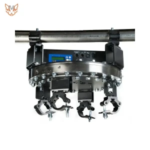
360° Rotating Motor
Equipment Overview The Giga Rotator by Wahlberg Motion is a heavy-duty rotary axis designed for suspended applications in stage, event, and performance environments. The unit is mounted to a load-bearing structure using four slim eye couplers , while the payload is connected to the lower rotating assembly. Its drive system enables objects to rotate around the suspension axis across a wide speed range, from slow movements at 0.02 rpm to speeds of up to 10 rpm . For performance configurations, the unit can be installed in either a vertical orientation or a horizontal orientation at 90° to the ground , allowing the projection surface to face the audience or creating dynamic spatial transformation effects. Rotation position, speed, and direction are controlled via DMX. The datasheet specifies 0.1° angular control resolution , making the unit suitable for motion sequences that require precise and repeatable positioning. Integration Principle The load-bearing suspension structure supports the weight of the unit and the performance payload. The motor and transmission system generate rotational torque around the vertical axis of the suspension assembly. The slip ring transfers 10 A per connection and allows Ethernet/DMX signals to pass through the rotating section, helping prevent cable twisting. The DMX controller sends position, speed, and cue commands. Motion should be tested under actual operating load conditions before deployment. Technical Specifications Specification Value Model DMX Rotator 1000 Item No. 282 Dimensions 485 × 485 × 244 mm Power Supply 100–240 VAC, 50/60 Hz Power Consumption 350 W (3.5–1.5 A) Power Input/Output Neutrik powerCON TRUE1 NAC3PX (F/M) Control Protocol DMX512/1990 + DMX512-A DMX Channels Used 7 channels DMX Input/Output 5-pin XLR (F/M) Thru Connection – Input powerCON TRUE1 (M) and EtherCON (F) Thru Connection – Rotating Section powerCON TRUE1 (F) and EtherCON (F) Power Thru 10 A per connection, 2.5 mm² conductor cross-section Signal Thru 100 Mbit Ethernet or DMX (optional RJ45 converter) Rotation Unlimited / continuous rotation Working Load – Downward 1,000 kg (2,204.6 lb) Working Load – Upward 1,000 kg (2,204.6 lb) Working Load – Horizontal Pending – not specified in the datasheet Rotational Speed 0.02–10 rpm Noise Level 50 dB at 1 m Ambient Temperature 5–40 °C Unit Weight 64.5 kg (142 lb) Mounting Clamps 4 × slim eye couplers, 42–52 mm (2 in) Duty Cycle 100% Control Characteristic Angular control with 0.1° accuracy Dimensions and Mechanical Interface Dimension / Mechanical Specification Value Overall Dimensions 485 × 485 × 244 mm Outer Housing Diameter Ø485 mm Reference Diameter – Top Surface Ø459 mm Top Hole Pattern Diameter Ø13 mm Bottom Connection Pattern Ø374 mm and Ø405 mm Threaded Connection Shown on Drawing M12 Hole Reference Angle 15° System Connections The unit receives DMX via a 5-pin XLR interface and uses 7 DMX channels . EtherCON and powerCON connections are routed through the rotating section, allowing power and signal transmission to equipment mounted on the rotating payload. This configuration is particularly useful for lighting fixtures, displays, cameras, and communication devices that need to remain operational while rotating. Performance Applications The Giga Rotator expands the range of motion possibilities for large suspended objects. Instead of relying solely on vertical lifting and lowering, the system can dynamically change the viewing direction, display surface, and form of a performance object over time. A 90° horizontal rotation can create a distinctive visual effect while remaining easy to synchronize with lighting, audio, video, and timecode. Operational Benefits A wide speed range supports both subtle movements and rapid scene transitions. Unlimited rotation eliminates travel limitations in designs requiring repeated multiple rotations. Power and signal pass-through through the rotary axis helps reduce the risk of cables wrapping around the structure. 0.1° angular control resolution supports precise and repeatable positioning.
View Details →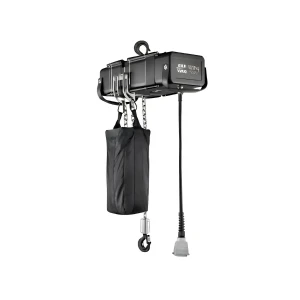
Suspension System Sliding Rail
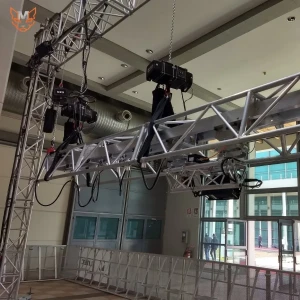
System Overview The DST52 is a rail-integrated stacking truss system developed for heavy-duty stage motion applications. It can be used to move LED screens, stage scenery, projection screens, and lighting assemblies horizontally. By adding a hoist or rotating module, the same platform can also provide lifting and lowering as well as 360° rotation . The DST52 is available in two rail configurations: straight and curved . A key feature of the DST52 is its stackable trapezoidal cross-section . The modules are connected using fork connections , allowing the trolley to be installed before the truss is suspended. This modular structure helps reduce setup time, minimize storage volume, and support the logistical requirements of touring productions. Technical Data – DST52 Rail Item Specification Structural type Trapezoidal-section stacking truss with dual rails Overall dimensions (H × W) 520–762 × 520 mm Centre-to-centre dimensions 470–712 × 470 mm Main chords EN AW-6082 T6 extruded aluminium, Ø50 × 4 mm Bracing tubes EN AW-6082 T6 extruded aluminium, Ø30 × 3 mm Fork connection EN AW-6082 T6 aluminium Rail configuration Straight or curved; trolley can operate on both types Finish Standard aluminium; dark grey or other colours available on request Standard Rail Sections LITEC Code Length / Geometry Weight STK52R100 100 cm 38.0 kg STK52R150 150 cm 51.0 kg STK52R300 300 cm 88.1 kg STK52RT100 100 cm 54.4 kg STK52RT150 150 cm 69.9 kg STK52RT300 300 cm 116.6 kg STK52RC Length ≤300 cm; radius ≥400 cm According to configuration Technical Data – STK52MTD2K The STK52MTD2K is a heavy-duty motorised trolley designed for the DST52 system. The trolley runs inside the dual-rail track and provides linear motion for the connected load, either in combination with a slave trolley or an auxiliary structure. This version is specifically characterized by a 1-ton WLL on 52R rail , a maximum speed of 21 m/min , and a Kinesys control interface . Item Verified Specification Equipment model STK52MTD2K Classification 52 cm DST Heavy Duty Motorised Trolley WLL on 52R rail 1,000 kg Maximum speed 21 m/min Equivalent speed 350 mm/s; 1.26 km/h Direction of travel Left-to-right / right-to-left Control interface Kinesys control interface DST52 Rail Load Table The table below presents two common loading cases based on the LITEC calculation data: uniformly distributed load (UDL) and a single point load at mid-span . The self-weight of the truss is already included in the allowable load values. These figures represent idealized static loading conditions, with the truss supported at both ends by the top chord . Span L (m) UDL q (kg/m) Total UDL (kg) Deflection (mm) Mid-span Point Load (kg) Deflection (mm) 3 1,760 5,290 2 4,410 3 6 725 4,350 14 2,180 11 9 315 2,830 31 1,420 25 12 171 2,050 56 1,030 45 15 105 1,570 87 784 71 18 68 1,230 125 616 104 21 47 980 170 490 144 24 33 781 222 391 191 Application limitations: The rail load table does not replace the need to verify localized loads at the trolley, fork connections, suspension points, and supporting structures. For moving loads, the design must account for dynamic factors, acceleration and deceleration distances, eccentric loading, and actual suspension conditions . Control and Stage Applications The Kinesys control interface allows the trolley to be integrated into a stage motion control system, enabling the programming of position, velocity, and synchronized movement cues . In a complete system, position feedback, software limits, mechanical end stops, and emergency stops should be designed as independent layers of protection. The compiled technical information also indicates that DST modules can be managed by other commonly used control systems available on the market; however, the interface configuration must be verified for each specific project. Moving LED Screens Move LED screens laterally to open the stage, change the stage layout, or create dynamic reveal effects. Scenery and Projection Screens Move stage scenery, portals, projection screens, or decorative frames over long travel distances. Touring Productions The stackable rail and foldable dolly configuration help optimize storage volume, simplify modular transportation, and accelerate setup on touring productions. Expandable Motion Systems Combine the system with a hoist for lifting and lowering or with an STK52MR module for 360° rotation. A dedicated technical assessment is required for combined configurations. Key Advantages 1,000 kg WLL for the motorised trolley on the 52R rail configuration. Maximum speed of 21 m/min , suitable for large-scale stage transitions. Straight and curved rail configurations to accommodate different stage geometries. Modular and stackable design , optimizing transportation and storage. Expandable architecture , allowing the system to evolve from Move to Move + Lift or Move + Turn configurations. Conclusion The DST52 Rail and STK52MTD2K Motorised Trolley form a modular heavy-duty stage motion platform suitable for applications requiring the long-travel movement of suspended equipment and structures. The DST52 supports both straight and curved rail configurations , while its stacking design helps optimize transportation and storage. The STK52MTD2K provides a 1,000 kg WLL and a maximum speed of 21 m/min , meeting the requirements of large-scale stage motion applications. The Kinesys control interface also enables the trolley to be integrated into a motion control system for programming position, velocity, and synchronized movement cues. When lifting or rotation is required, the DST52 platform can be further expanded with suitable modules. However, for every real-world configuration, equipment selection, load capacity, connections, supporting structures, and safety systems must be engineered and verified according to the technical documentation and requirements of each individual project , particularly when the system operates with moving loads.
View Details →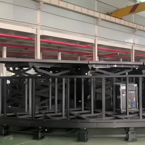
Combined Rotary and Lifting Stage
Combined 360° Rotation and Independent Vertical Lifting ROTATIONAL MOTION LIFTING MOTION CONTROL Ø4–18 m · 1–6 rpm Multiple independent lift modules Cue · Position · Speed · Timecode Key Value: A single stage system can simultaneously rotate the overall stage while changing the elevation of individual areas, enabling continuous scene transitions without interrupting the performance. What Is a Rotary Stage Combined with Programmable Stage Lifts? Combining a rotary stage with programmable stage lifts introduces a new level of flexibility to motion-stage design. The modular rotary stage can be configured from approximately 4 m to 18 m in diameter , using multiple coordinated 2 HP motors with an adjustable rotational speed of approximately 1–6 rpm . Within the circular structure, multiple programmable stage-lift modules can be arranged as independent zones, allowing performers, props or sections of the scenery to move vertically while the entire stage continues to rotate. Each stage-lift module can be customized according to project requirements , including its shape, platform dimensions, lifting stroke, working load, operating speed and number of drive points. The motion-control system can program target position, speed, acceleration, timing, cue and timecode, allowing the lift modules to coordinate with the rotary movement according to a unified show sequence. The working load of each lift module is calculated after deducting the self-weight of the moving structure. Eccentric loads, dynamic factors and safety margins must also be taken into consideration. This configuration creates a 360° stage effect , continuous scene transitions and real-time elevation changes during a performance. The director can raise a singer from below the stage, rotate the band toward the audience, reposition props or create multiple spatial layers without interrupting the show. This configuration is suitable for concerts, game shows, festivals and large-scale stages requiring complex motion capabilities. Technical Data – Modular Rotary Stage Specification Technical Data Notes System type Modular rotary stage Reconfigurable according to project requirements Diameter Approximately Ø4 m to Ø18 m Final dimensions determined by venue layout and load requirements Structure Fan-shaped modules, radial beams and concentric rings Demountable for transportation Rotational speed Approximately 1–6 rpm, adjustable via PLC 6 rpm is not applicable to every diameter Rotation direction Clockwise/counterclockwise; 360° rotation according to configuration Direction changes managed through controlled acceleration/deceleration profiles Control PLC Supports cue and show control Surface finish Plywood, vinyl, carpet or other finishing materials Selected according to the artistic design Safety E-stop, speed limits, pinch-point protection and drive monitoring To be assessed and validated for each project Speed Consideration: At Ø18 m , 1 rpm corresponds to an approximate edge speed of 0.94 m/s , while 6 rpm corresponds to approximately 5.65 m/s . Therefore, the maximum rotational speed must be limited according to the stage diameter, load conditions and performer location. Technical Data – Customized Programmable Stage Lifts Specification Reference Data Notes System name Customized programmable stage lift Individually designed for each project Platform shape Circular, square, rectangular or special shapes Coordinated with the rotary-stage modules Platform dimensions Customized according to the stage design Final dimensions determined by drawings and installation space Lifting stroke Customized according to the required elevation Dependent on structural configuration and available technical space WLL Calculated according to the actual module load Includes performers, props and concentrated loads Lifting/lowering speed Programmed and limited according to the application Smooth motion is prioritized when performers are present Number of lift modules One or multiple independent modules Can operate individually or in groups Number of drive points Designed according to dimensions and load distribution Ensures synchronized elevation Position feedback Encoder/position sensor Monitors elevation and positional deviation Programming Position, speed, acceleration, timing, cue/timecode Enables coordination of multiple motion axes Useful load capacity Lifting capacity after deducting the self-weight of the moving structure Accounts for eccentric loads and dynamic factors Safety equipment E-stop, travel limits, anti-drop protection and synchronization monitoring Final configuration determined through risk assessment Load Principle: The WLL (Working Load Limit) of each stage-lift module must be established based on the structural design, number of drive points, self-weight, load position, dynamic loads and applicable safety factors. A single standardized load rating should not be applied to all module sizes. Conclusion A rotary stage combined with programmable stage lifts expands the possibilities of motion-stage design by integrating two primary movements: full-stage rotation and independent vertical lifting of individual areas . With a modular structure, customized lift modules and PLC-based control, the system can be engineered according to the specific venue layout, load requirements, lifting stroke, operating speed and motion sequence of each project. For stable and safe operation, parameters such as rotational speed relative to stage diameter, working load limit (WLL), eccentric loads, dynamic loads, number of drive points, elevation synchronization and protective devices must be calculated and validated according to actual operating conditions. In particular, a fixed rotational speed or load rating should not be applied universally across all configurations. When properly designed, programmed and controlled according to the required technical specifications, the system can deliver 360° scene transitions, dynamic elevation changes and continuous spatial reconfiguration without interrupting the performance. This makes it a suitable solution for modern stages requiring advanced mechanical motion, automation and show-control synchronization .
View Details →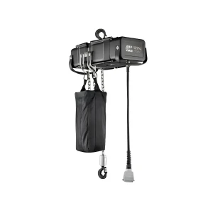
Stage Rotating Platform
What Is a Modular Rotating Stage? The modular rotating stage supplied by Melody Productionworx is a flexible motion-stage solution developed to accommodate different event scales and production requirements. Instead of manufacturing a fixed rotating stage for each project, the system uses fan-shaped modules, radial beams, and concentric structural rings. Starting from a configuration of approximately 4 m in diameter, the stage can be progressively expanded to 18 m by adding the appropriate modules, rails, wheels, and drive units. The drive system uses multiple 2 HP motors working together. This multi-drive configuration distributes pulling force around the circumference, reducing concentrated loads and allowing the drive capacity to be scaled according to the stage diameter, overall weight, and performance load. The motors are controlled through variable frequency drives (VFDs), combined with PLC control and encoders to provide smooth motion, variable speed control, forward and reverse rotation, and precise stopping according to programmed show cues. The rotation speed can be adjusted from approximately 1 rpm to 6 rpm. However, the actual operating speed is always determined according to the stage dimensions, load conditions, performance requirements, and applicable safety considerations. One of the system's key advantages is its flexibility for both production and repeated use. The same set of modules can be configured for concerts, game shows, product launches, automotive exhibitions, fashion events, or performing arts productions. The detachable construction facilitates transportation, reduces installation time, and allows individual components to be serviced or replaced when required. The stage surface can also be finished with a range of materials to match the overall visual design of the production. With the ability to scale to large diameters, the rotating stage can transform not only a single prop or performance element but the entire performance space into an active staging component. Scenic elements, performers, or products can be brought into the audience's field of view in sync with the show sequence, creating a 360° presentation effect and expanding creative possibilities for directors and production teams. Each project is individually engineered according to the required load capacity, venue layout, operating speed, staging concept, and safety requirements. This ensures that the system delivers the desired performance effect while maintaining controlled and predictable operation. Solution Overview The modular rotating stage is a motion-stage system developed for concerts, television productions, festivals, exhibitions, and live events that require real-time changes in spatial configuration. Unlike a fixed rotating stage designed for a single diameter, the system uses fan-shaped structural modules, radial beams, and concentric structural rings. This allows the stage diameter to be configured from approximately 4 m to 18 m according to the venue layout, load requirements, and staging concept. Each configuration consists of a central hub, modular structural frames, support wheels, running rails, and drive assemblies. When a larger diameter is required, the technical team adds outer modular rings, extends the rail system, and installs additional 2 HP motors to maintain adequate traction and distribute torque evenly around the circumference. Key Technical Specifications Item Technical Description Configurable Dimensions Diameter configurations from approximately 4 m to 18 m; the final diameter is determined according to the approved layout drawings. Modular Structure Fan-shaped frames connected to form concentric rings; detachable for transportation and reconfiguration. Reference Frame The 18 m reference drawing specifies 40 × 80 × 1.4 mm rectangular steel tubing; final material dimensions are subject to structural load calculations. Running Rails The reference drawing uses 3 mm-thick sheet-metal rails; rail flatness, joint conditions, and wear resistance must be verified for each installation. Drive System Multiple 2 HP motors (approximately 1.5 kW per motor), arranged according to the stage size and load requirements. Rotation Speed Adjustable from approximately 1 rpm to 6 rpm through VFD control and programmed motion control. Rotation Direction Clockwise and counterclockwise rotation; direction changes must be performed through a controlled deceleration and stopping profile. Stage Surface Finish Can be finished with plywood, steel, vinyl, carpet, or other decorative materials suitable for the stage design. Control System PLC/VFD, encoders, and safety interlocks; programmable operating cues can be integrated into the show control sequence. Modular Construction and Scalability Scalability is one of the system's core advantages. The structure is divided into several functional layers: Central Hub and Positioning Assembly: Establishes the rotational center, maintains concentricity, and carries part of the radial load. Radial Beams: Distribute loads from the stage surface toward the supporting rings and provide the primary structural framework for the fan-shaped modules. Concentric Structural Rings: Added progressively to increase the stage diameter. The 18 m reference drawing shows ring positions at approximately 4, 6, 8, 10, 12, 14, and 16 m before reaching the final outer diameter. Stage Deck Modules: Fan-shaped deck panels installed on the structural frame, allowing the deck surface and finish to be removed, replaced, or reconfigured. Support Wheels and Running Rails: Carry vertical loads, maintain the required deck elevation, and provide a stable rotational path. Drive Assemblies: 2 HP motors, gearboxes, and drive wheels distributed at multiple locations to share the required torque. Advantages of a Modular Rotating Stage Scalable Configuration: A single modular system can serve multiple event formats instead of requiring a dedicated fixed rotating stage for each project. Optimized Investment: Structural frames, rails, wheels, and drive units can be reused and expanded according to the requirements of each project. Efficient Transportation: Fan-shaped modules and detachable beams are easier to package and transport than a monolithic structure. Faster Installation: Components can be labeled and assembled ring by ring, facilitating on-site installation and progress control. Simplified Maintenance: Individual motors, wheels, rails, and structural modules can be inspected and replaced independently. High Visual Impact: Supports scene transitions, performer rotation, moving props, display vehicles, product presentations, or rotation of the entire performance space. Applications in Live Events and Entertainment A rotating stage creates continuous movement without requiring camera positions to be changed or scenic elements to be dismantled between performance segments. In concerts, the system can rotate bands, performers, props, or secondary stage platforms to create dynamic 360° viewing angles. For television productions and product launches, the rotating stage allows cameras to capture multiple viewing angles while turning vehicles, products, or models into an active part of the presentation. With a large-diameter configuration, the stage can also be divided into multiple scenic zones, allowing different environments to be brought into the audience's field of view in sequence. Conclusion A modular rotating stage provides a more flexible alternative to a fixed rotating stage by allowing the system to be dismantled, reconfigured, and expanded according to individual project requirements. From approximately Ø4 m to Ø18 m, the system can be engineered with the appropriate number of modules, structural rings, support wheels, rails, and drive assemblies based on the actual load conditions and venue layout. The combination of modular mechanical construction with PLC/VFD and encoder-based control enables precise management of rotation, speed, and direction according to the show sequence. This makes the solution suitable for stages that require 360° movement, flexible scene transitions, and large-scale visual effects. Each system should be individually engineered and verified according to the required load capacity, operating speed, venue layout, and safety requirements before being put into operation.
View Details →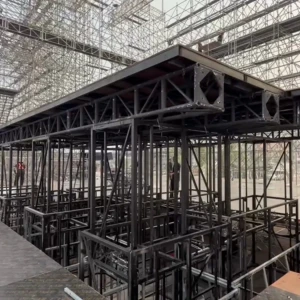
Cable-Driven Stage Lift
Solution Overview 1. Capabilities Shape: Rectangular, square, circular, curved, polygonal, or other custom profiles based on architectural drawings. Dimensions: Available as a single platform or modular configuration; the structure can be disassembled, transported, and reconfigured as required. Load Capacity: Determined based on WLL, load distribution, point loads, dynamic loads, and actual operating conditions. Movement: Vertical lifting, multiple stopping levels, synchronized operation, or independently controlled zones. Floor Finish: Film-faced plywood, carpet, or other stage flooring finishes as required. 2. Typical Applications Application Operating Objective Reference Configuration Performance Stage Raise performers or stage props from below the stage floor Recessed stage lift platform with multiple stopping levels Event Stage Create different elevations and transform the stage layout Modular platforms with synchronized control Exhibitions / Vehicle Launches Elevate products and create dynamic reveal effects Custom-shaped platform with smooth movement Multipurpose Auditorium Transform the functionality and layout of the floor area Multiple independent lift platforms with sensor-based locking Proposed System Architecture HMI / Push-Button Command → Safety PLC Controller → Variable Frequency Drive (VFD) / Motor Starter → Drive Mechanism → Lifting Platform + Guide Rails Conclusion A customized stage lift platform provides a high degree of flexibility for creating different elevations, transforming layouts, and delivering reveal effects in stages, events, exhibitions, and multipurpose spaces. With customizable dimensions, load capacity, lifting travel, speed, modular configuration, and control systems , the solution can be developed to suit the architectural characteristics and operational scenarios of each project. For actual implementation, the technical requirements, loading conditions, structural design, control system, and safety protection measures must be further defined to develop an appropriate engineering design and manufacturing documentation.
View Details →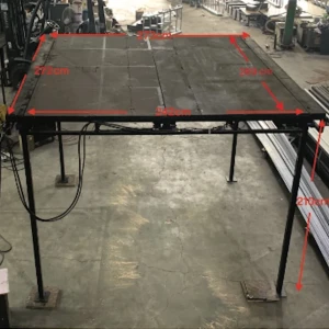
Rail-Guided Recessed Stage Lift
Scope and Intended Use The proposed system is a recessed stage lift installed within a technical pit. When in the lowered position, the platform is located below the stage floor level. When fully raised, the platform is aligned flush with the stage floor, allowing props, equipment, or performers to be brought to the performance position. Applications: Performance stages, studios, multipurpose rooms, and performance areas where the lifting mechanism needs to be concealed. Operating mode: Operator-controlled raising/lowering. The system must not operate automatically when the operating area has not been secured. WLL 250 kg: Defined as the useful load uniformly distributed across the platform, excluding the self-weight of the platform and moving mechanism. Limitation: The system must not be used as a public passenger lift. If performers are to be lifted, an additional risk assessment, an independent fall-arrest system, and compliance with applicable regulations and standards are required. Preliminary Technical Specifications Parameter Preliminary Value Status Overall frame dimensions 2,000 × 2,000 mm As per drawing Usable platform dimensions Approx. 1,600 × 1,800 mm As per drawing Lifting stroke 2,000 mm As per drawing Base assembly height Approx. 240 mm As per drawing WLL 250 kg, uniformly distributed load As required Speed 10 m/min (0.167 m/s) Assumed – to be confirmed Travel time for 2 m Approx. 12 seconds Calculated from speed Motor shown on drawing 1 HP ≈ 0.75 kW Requires verification Main structure 40 × 80 mm and 50 × 100 mm box sections As per drawing Drive system Motor + gearbox + twin chain + gear/rack drive on both sides As per drawing Guidance system Guide rollers at the corners As per drawing Power supply / duty rating Not yet specified To be defined Mechanical Construction Assembly Function / Requirement Fixed pit frame Provides the guide rails, accommodates lateral loads, and connects to the stage structure. Lift platform Constructed from 50 × 100 mm box sections, supporting the finished surface and transferring loads to the drive assemblies on both sides. Geared motor Generates the lifting torque; an electromagnetic brake motor with variable frequency drive (VFD) is recommended. Twin shaft / chain drive Distributes motion synchronously to both sides to minimize platform tilting. Gear and rack mechanism Converts rotary motion into vertical linear motion. Guide rollers Restrict lateral movement, maintain the required clearances, and prevent jamming. 100 × 150 × 10 mm mounting plate Connects the rack to the frame; dimensions and welds must be verified for load-bearing capacity. Operating Principle Command input: The PLC checks the E-stop, technical pit/door status, sensors, and brake condition. Brake release and acceleration: The VFD controls motor acceleration according to a predefined ramp to minimize shock and vibration. Torque transmission: The gearbox transfers torque to the twin shaft/chain drive, driving the gears on both sides. Synchronized lifting/lowering: The gears engage with the racks while the guide rollers maintain the platform in a level position. Deceleration and stopping: Position sensors initiate deceleration before reaching the floor level, while limit switches ensure accurate stopping at the operating limits. Load holding: The motor brake engages, while an independent anti-fall mechanism provides protection in the event of a system failure.
View Details →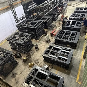
60R Series Chain Lift Stage Platform
General Specifications – 60R Series Specification Details Maximum height 5,500 mm Minimum height 1,000 mm Effective lifting stroke 5,000 mm Platform dimensions (L × W × H) 1,980 × 3,158 × 900 mm Weight per lifting platform 2,900 kg Maximum lifting speed Not specified in the available source summary 60R Model Specification Details / Description Platform dimensions (L × W × H) 1,980 × 3,158 × 900 mm Working height 1,000–5,500 mm Lifting stroke 5,000 mm Lifting platform weight 2,900 kg Maximum lifting speed Data not available in the source table Applications A programmable stage lift is an important automation system for live performances, concerts, theaters, television productions, and large-scale events. It enables performers, stage props, musical instruments, or individual stage sections to be raised and lowered according to pre-programmed positions, speeds, and timing sequences. The movements can be triggered by cues or synchronized with the timecode of music, lighting, and visual content, creating impressive effects for performer entrances, spatial transformations, and scene transitions. When multiple stage lifts are integrated into a single system, directors can create multi-level stage configurations, ramps, performance platforms, and coordinated sequential movements . Beyond visual effects, stage lifts can also reduce scene-change time, minimize manual labor, and improve movement accuracy and consistency between performances. For safe operation, the system should be equipped with position sensors, travel limits, load monitoring, emergency stop controls, and mechanisms for detecting discrepancies between lifting points . The allowable load must be determined based on the actual working height and lifting stroke and should account for performers, stage props, surface finishes, and all accessories moving with the platform. Conclusion The Chain Lift 60R Series programmable stage lift meets the requirements for precise and flexible vertical movement in modern stage systems. With a lifting stroke of up to 5,000 mm and a working height ranging from 1,000 to 5,500 mm , the system can be used to raise performers, stage props, musical instruments, or create multi-level stage structures according to the show's programmed sequence. For actual project implementation, the appropriate configuration should be selected based on the required load capacity, lifting stroke, and synchronization requirements of each project. The system should also incorporate comprehensive position monitoring, travel-limit protection, load monitoring, and emergency-stop functions to ensure stable, accurate, and safe operation.
View Details →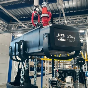
Palang lập trình EXE 500 kg Vario Variable Speed Chain Hoist D8
Thông số kỹ thuật palang Hạng mục Thông số / mô tả Tải làm việc (Working Load Limit - WLL) 500 kg Tốc độ nâng tại 50 Hz 20 m/phút Công suất động cơ 2,2 kW Điện áp vận hành đấu Y 400 VAC, 3 pha, 50 Hz Dòng điện ở 3 pha 400 VAC Xấp xỉ 6 A Tốc độ quay 2.800 vòng/phút Số nhánh xích 1 Puly tải / đĩa xích 5 hốc xích Cấp bảo vệ IP55 theo DIN 40050 Phân loại FEM 1Bm Hệ số làm việc của động cơ 25% Số lần khởi động mỗi giờ 150 Chiều dài cáp kết nối 1 m Đầu nối nguồn đấu Y CEE 16 A, 6h, 400 VAC, 3PH + G, phích màu đen Độ ồn 67,5 dB khi đầy tải Số phanh DC 2 Kích thước phanh DC 10 Công suất phanh DC 30 W Điện áp vận hành phanh DC 205 VDC Mô-men định mức phanh DC 16 Nm Giảm mô-men định mức tại tốc độ chỉ định 76% tại 3.000 vòng/phút (mốc chỉ định 1.500 vòng/phút) Đặc tính ly hợp Bộ giới hạn lực dựa trên ma sát; ly hợp nằm ngoài đường truyền chuyển động. Khối lượng bản thân Xấp xỉ 45,0 kg 2. Thông số xích và túi xích Thông số xích Thông số xích Giá trị Kích thước xích 8 x 24 mm Hệ số an toàn 5:1 Khối lượng xích 0,39 kg/m Vật liệu Thép mạ kẽm cấp 80 Cỡ túi xích Cỡ túi / phạm vi Khối lượng Kích thước ngoài Chiều cao M - chiều dài xích đến 26 m 1 kg 200 x 170 mm 420 mm L - chiều dài xích 26-40 m 1 kg 200 x 170 mm 580 mm XL - chiều dài xích đến 40 m 1 kg 270 x 210 mm 650 mm 3. Chức năng điều khiển và đồng bộ hệ thống Vector Console biến palang EXE Vario thành hệ chuyển động sân khấu có thể lập trình theo cue. Người kỹ thuật thiết lập vị trí đích, tốc độ, gia tốc, thời gian và liên kết nhiều trục để tạo chuyển động đồng bộ. Cue có thể chạy riêng, nối chuỗi hoặc kích hoạt theo trình tự. Timecode cho phép cue bám theo mốc thời gian của chương trình, giúp chuyển động khớp với âm thanh, ánh sáng và video. PosiStageNet (PSN) là giao thức mạng mở truyền dữ liệu vị trí 3D theo thời gian thực. Khi Vector xuất vị trí của từng trục qua PSN, media server có thể nhận tọa độ, ánh xạ vào vật thể ảo và cập nhật nội dung theo chuyển động thực tế. 4. Luồng kết nối tham khảo Thiết bị Thiết bị / hệ thống kết nối Palang EXE Vario Kinesys Elevation / mạng điều khiển Kinesys Elevation / mạng điều khiển Vector Console / Vector Software Vector Console / Vector Software Media server (ví dụ: Disguise) Lưu ý: Việc xuất/nhận PSN hoặc driver chuyên dụng phụ thuộc phiên bản phần mềm, cấu hình mạng và media server sử dụng. Luôn xác minh cấu hình với tài liệu kỹ thuật hiện hành trước khi triển khai show. Kết luận EXE Vario 500 kg D8 là palang xích tốc độ biến thiên hướng đến các hệ thống nâng hạ và chuyển động sân khấu chuyên nghiệp, trong đó yêu cầu không chỉ dừng ở khả năng nâng tải mà còn cần kiểm soát chính xác vị trí, tốc độ và trình tự chuyển động. Với tải làm việc 500 kg, tốc độ nâng 20 m/phút, động cơ 2,2 kW, hai phanh DC và khả năng kết hợp với hệ thống điều khiển như Vector Console, thiết bị có thể đáp ứng các cấu hình chuyển động được lập trình theo cue và timecode. Khi triển khai thực tế, cần lựa chọn đúng cấu hình palang, xích, túi xích, hệ thống điều khiển và mạng kết nối theo yêu cầu của từng chương trình. Các thông số về tải, hệ số an toàn, cấu hình điện và khả năng tích hợp phần mềm cũng cần được kiểm tra theo tài liệu kỹ thuật hiện hành của nhà sản xuất trước khi đưa thiết bị vào vận hành.
View Details →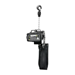
Synchronized Hoist
Technical Specifications Item Specification Product model RH-1000S4 Equipment type D8 electric chain hoist Safe working load 1,000 kg Control type Direct Control Operating voltage AC 400 V / 50 Hz, 3-phase Motor 0.75 kW × 4P (4-pole motor) Lifting speed at 50 Hz 4 m/min Lifting speed at 60 Hz 4.8 m/min Number of chain falls 1 Load chain Grade 80; 7.1 × 20.2 mm; compliant with EN 818-7 Duty classification FEM 2m / ISO M5 Duty cycle ED 40% Starts per hour 240 Enclosure rating IP54 Hoist weight 47 kg, excluding load chain Power cable 3 m long, red 4-pin CEE connector Operating noise level 75 dB(A), measured at a distance of 1 m Applicable standards / guidelines BGV D8 / IGVW SQP2:2018 Structural and Safety Features Component / Function Technical Description Heavy-duty DC brake A spring-applied DC electromagnetic brake automatically holds the load in the event of power loss or a malfunction. The design is intended for low maintenance requirements, with only minor periodic adjustments required. Overload-protection friction clutch The friction clutch helps protect the transmission mechanism when the load exceeds the permitted threshold, reducing the risk of damage to the hoist and rigging system. IP54 enclosure The enclosure provides limited protection against dust and protection against water splashes from various directions, making it suitable for stage environments when operated within the manufacturer's specified conditions. Standard-compliant load chain Only Grade 80, 7.1 × 20.2 mm chain compliant with EN 818-7 should be used. The chain link dimensions, pitch, and sprocket geometry must be precisely compatible. Load hook The rigging hook can swivel and is equipped with a safety latch. It should be inspected before each use in accordance with the inspection procedures established by the operating organization. Suitable Applications Rigging for concerts, events, and touring productions. Lifting and suspending lighting equipment, line-array speaker systems, and stage structures. Theatrical props, scenic elements, and television production stages. Permanent installations in theaters and performance venues. Overhead lifting applications where the D8 classification and control configuration are appropriate for the approved rigging plan. Direct Control and Multi-Hoist Operation The RH-1000S4 receives power and direct forward/reverse commands through a compatible control system using a 4-pin CEE connector. When multiple hoists are connected to a direct-control hoist control panel, the operator can issue lifting or lowering commands to a group of hoists. However, receiving the same command does not necessarily mean that the hoists will maintain precisely synchronized positions. Differences in load, voltage, chain elongation, and brake characteristics can result in variations in travel distance. If the application requires multiple lifting points to maintain the same elevation or perform controlled positional movements, a suitable solution incorporating travel measurement/encoders, load monitoring, and a control system designed for synchronized movement is required. Reference Dimensions Dimension Value Shown in Manufacturer's Drawing Overall height shown in drawing 650 mm Horizontal body length 247 mm + 221 mm Hoist body height 156 mm Upper hook area dimensions 105 mm + 185 mm Hook dimensions 23 mm / 30 mm / 33 mm, depending on the position shown in the drawing Accessories and Compatibility Compatible with direct-control hoist cables and control panels using a red 4-pin CEE connector. Accessories specified by KUPO include the RH-1000-1 W flight case and CH-52B protective cover . For low-voltage centralized control, the manufacturer recommends selecting the RH-1000LV instead of the RH-1000S4. Compared with the RH-1000S8 , the RH-1000S4 operates at a lower speed of 4 m/min, making it suitable for applications where standard lifting speed and easier movement control are preferred. Important Notes on the D8 Classification Important: The D8 classification refers to the equipment classification, while its use must comply with the applicable rigging plan, safety procedures, secondary safety requirements, and regulations in force at the venue. The D8 classification should not be interpreted as automatically permitting scenic movement above people. The selection, installation, operation, inspection, and maintenance of the hoist must be carried out by competent and appropriately qualified personnel . Conclusion The KUPO RH-1000S4 is a suitable choice for rigging systems requiring a 1,000 kg D8 electric chain hoist with Direct Control and a standard lifting speed of 4 m/min . Designed with stage environments in mind, the hoist combines a heavy-duty DC brake, overload-protection friction clutch, Grade 80 load chain, and FEM 2m / ISO M5 duty classification to support the lifting and suspension of stage equipment, structures, and scenic elements when implemented according to an appropriate technical rigging plan. However, hoist selection and operation should not be based solely on the 1,000 kg rated load or D8 classification . The operating organization should assess the actual load, rigging configuration, control system, installation conditions, secondary safety requirements, and applicable safety regulations in full. For synchronized movement across multiple lifting points or precise positional control, an appropriate control and monitoring solution should be used rather than simply grouping multiple hoists through a Direct Control configuration.
View Details →Featured Case Studies
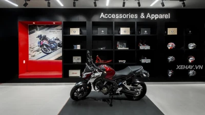
Dự Án Trang Trí Quảng Cáo Và Nhận Diện Thương Hiệu Garage Honda Motor
Đội ngũ MPX đã hoàn thành dự án trang trí quảng cáo và nhận diện thương hiệu tại xưởng bảo dưỡng của Honda Motor. Chúng tôi ứng dụng các vật liệu hiện đại nhằm nâng tầm hình ảnh chuyên nghiệp cho khu vực phục vụ khách hàng. Dự án đáp ứng trọn vẹn tiêu chuẩn thẩm mỹ khắt khe từ hãng xe hàng đầu Nhật Bản.
View Details →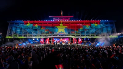
MPX Thi Công Khán Đài Diễu Binh Và Sân Khấu Nổi Đại Lễ 30/4/2025 Tại TP.HCM
Đội ngũ kỹ sư MPX đã hoàn thành xuất sắc dự án thiết kế và thi công chuỗi hạng mục trọng điểm phục vụ Đại lễ 30/4/2025 tại Thành phố Hồ Chí Minh. Chúng tôi trực tiếp triển khai hệ thống khán đài diễu binh sức chứa lớn và sân khấu nghệ thuật nổi trên mặt nước. Kết quả đạt được là một hệ thống kết cấu vững chắc, đảm bảo an toàn cho hàng nghìn người dân và du khách tham dự sự kiện.
View Details →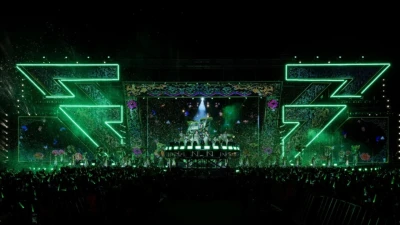
MPX Thiết Kế Kết Cấu & Thi Công Cơ Khí Sân Khấu Concert Chị Đẹp Đạp Gió Rẽ Sóng 2025
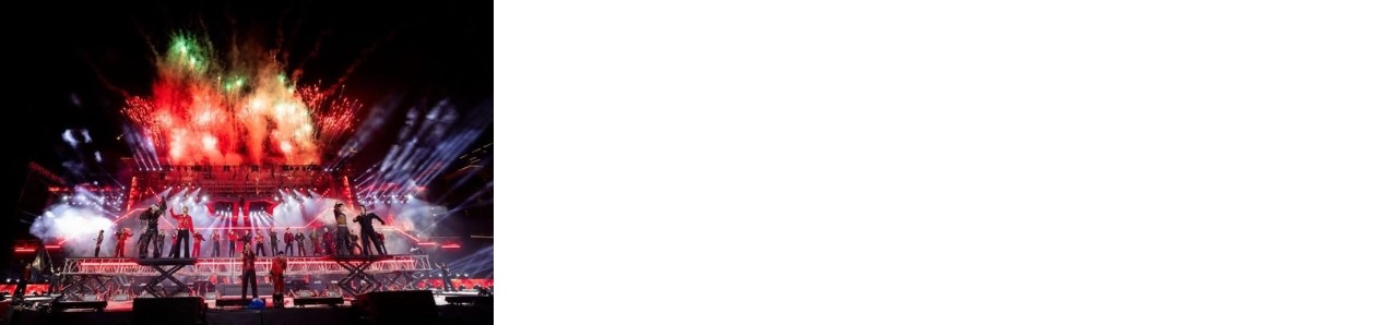
Đội ngũ kỹ sư MPX đã hoàn thành xuất sắc hạng mục thiết kế kết cấu và thi công cơ khí sân khấu cho Concert Chị Đẹp Đạp Gió Rẽ Sóng 2025. Tại sự kiện quy mô 30.000 khán giả này, chúng tôi đã triển khai hệ thống cầu nâng xoay 360 độ cùng các bàn nâng tự động phức tạp. Các giải pháp kỹ thuật chính xác tuyệt đối đã mang lại những màn trình diễn nghệ thuật đẳng cấp và an toàn cho 48 nữ nghệ sĩ.
View Details →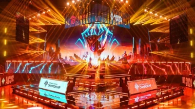
Thi Công Sân Khấu Chung Kết AIC 2024: Giải Pháp Kết Cấu eSports Đẳng Cấp Quốc Tế
Đội ngũ kỹ sư MPX đã hoàn thành xuất sắc hạng mục thiết kế kết cấu và thi công sân khấu cho trận chung kết Arena of Valor International Championship (AIC) 2024 . Chúng tôi cung cấp giải pháp cơ khí chịu lực tải trọng cao để nâng đỡ hệ thống màn hình LED khổng lồ cùng thiết bị trình diễn công nghệ tiên tiến. Dự án đã góp phần tạo nên không gian thể thao điện tử đẳng cấp phục vụ hàng triệu khán giả trên toàn cầu.
View Details →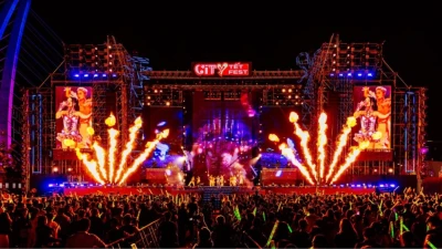
MPX Thi Công Sân Khấu Và Hạ Tầng Sự Kiện City Tết Fest 2024
Đội ngũ kỹ sư MPX đã hoàn thành xuất sắc dự án thi công sân khấu và hạ tầng sự kiện chính cho chương trình City Tết Fest 2024. Chúng tôi cung cấp giải pháp cơ khí chịu lực toàn diện nhằm kiến tạo một khu vực lễ hội hiện đại giữa trung tâm thành phố. Kết quả đạt được là một hệ thống thiết bị vững chãi, bảo đảm an toàn tuyệt đối cho hàng ngàn khán giả tham dự.
View Details →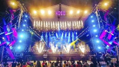
Thi Công Hệ Thống Sân Khấu Hò Dô Festival 2024 Với Giàn Truss Chịu Tải Trọng Lớn
Đội ngũ MPX đã hoàn thành xuất sắc hạng mục thi công hệ thống sân khấu trung tâm cho lễ hội Hò Dô 2024 tại phố đi bộ Nguyễn Huệ. Chúng tôi cung cấp giải pháp giàn truss nhôm chịu tải trọng lớn phục vụ hệ thống màn hình LED và thiết bị chiếu sáng. Dự án đáp ứng các tiêu chuẩn kỹ thuật khắt khe nhất dành cho sự kiện âm nhạc ngoài trời quy mô hàng vạn khán giả.
View Details →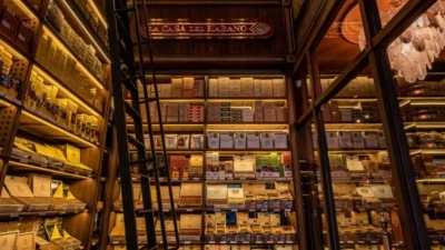
Dự Án Thi Công Nội Thất Cửa Hàng Xì Gà Habanos Tại Hai Bà Trưng, Hà Nội
Đội ngũ kỹ sư MPX đã hoàn thiện dự án thi công nội thất trọn gói cho cửa hàng xì gà Habanos tại trung tâm quận Hai Bà Trưng, Hà Nội. Chúng tôi mang đến một không gian trải nghiệm đẳng cấp, phản ánh đúng giá trị di sản của thương hiệu. Giải pháp vật liệu gỗ cao cấp kết hợp đồng thau nguyên bản tạo nên sự sang trọng tuyệt đối cho tổng thể công trình.
View Details →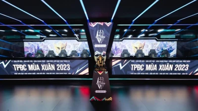
Dự Án Thi Công Sản Xuất Không Gian Và Lắp Đặt Tranh Trang Trí Cho Studio Garena Tại Trung Sơn
Đội ngũ kỹ sư MPX đã hoàn thành xuất sắc dự án thi công sản xuất không gian và lắp đặt hệ thống tranh ảnh trang trí cho studio Garena tại khu vực Trung Sơn. Dự án tập trung vào giải pháp bố trí đồ họa thương hiệu kết hợp hệ khung treo chịu lực an toàn. Kết quả mang lại một không gian làm việc sáng tạo, thẩm mỹ và truyền tải trọn vẹn tinh thần cốt lõi của doanh nghiệp.
View Details →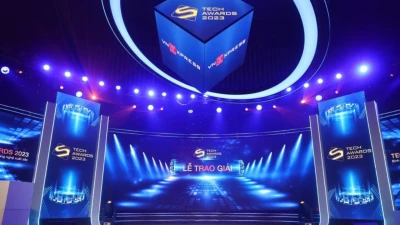
MPX Triển Khai Hệ Thống Khung Truss Cho Tech Awards 2023
Đội ngũ kỹ sư MPX đã triển khai thành công hệ thống khung truss hợp kim nhôm chuyên dụng cho chương trình Tech Awards 2023. Chúng tôi trực tiếp thiết kế kết cấu chịu lực nhằm đáp ứng khối lượng thiết bị âm thanh và màn hình LED cỡ lớn. Giải pháp kỹ thuật này mang lại một không gian sân khấu công nghệ hiện đại và an toàn tuyệt đối.
View Details →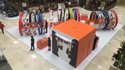
Dự Án Thi Công Gian Hàng Hermès Tại Takashimaya Saigon Chuẩn Cao Cấp
Đội ngũ kỹ sư MPX đã hoàn thành dự án thi công gian hàng Hermès tại Takashimaya Saigon. Dự án yêu cầu độ chính xác tuyệt đối về kết cấu chịu lực và mức độ hoàn thiện thẩm mỹ. Kết quả mang lại một không gian trưng bày vững chắc, đáp ứng trọn vẹn tiêu chuẩn của thương hiệu xa xỉ.
View Details →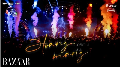
Thi Công Sân Khấu Gameshow Our Song VieON – Dự Án Trường Quay Do MPX Thực Hiện
Đội ngũ kỹ sư MPX đã hoàn thiện dự án sản xuất và thi công sân khấu cho chương trình giải trí Our Song do VieON sản xuất. Chúng tôi cung cấp giải pháp toàn diện từ hệ thống khung truss chịu lực đến cảnh trí trường quay chuẩn phát sóng. Kết quả mang lại một không gian biểu diễn hiện đại, đáp ứng trọn vẹn các yêu cầu khắt khe của ngành công nghiệp truyền hình.
View Details →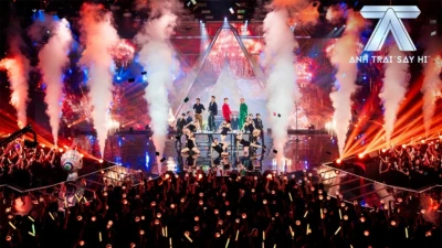
Thi Công Sân Khấu Gameshow Anh Trai Say Hi: Giải Pháp Kết Cấu Và Cảnh Trí Truyền Hình
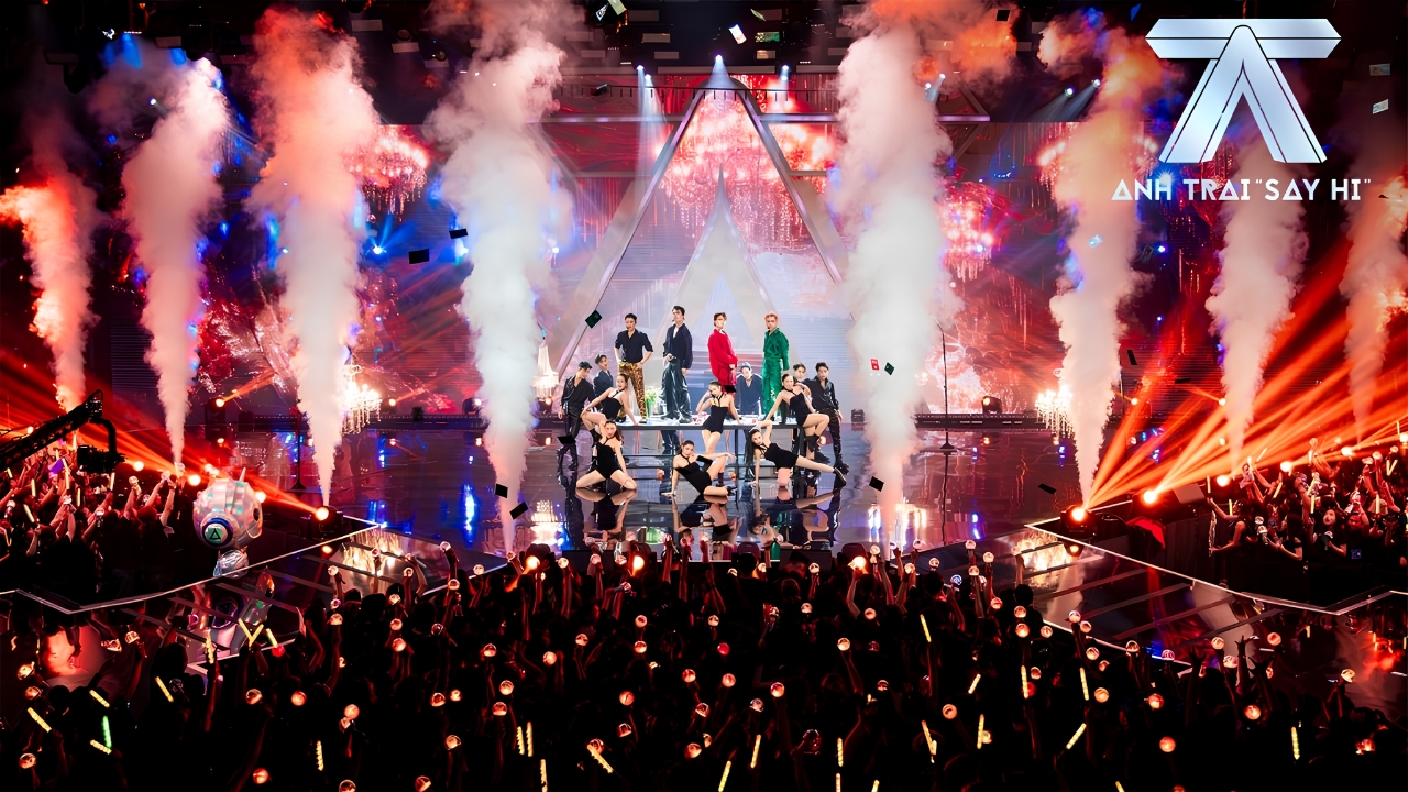
Đội ngũ kỹ sư MPX đã hoàn thiện toàn bộ hệ thống sân khấu và cảnh trí cho gameshow "Anh Trai Say Hi" do nền tảng VieON phát hành năm 2024. Chúng tôi áp dụng hệ thống kết cấu mô-đun linh hoạt để đáp ứng yêu cầu chuyển cảnh liên tục của một chương trình truyền hình thực tế quy mô lớn. Dự án đã tạo ra một không gian ghi hình sinh động, tương tác tốt và mang đậm dấu ấn thương hiệu.
View Details →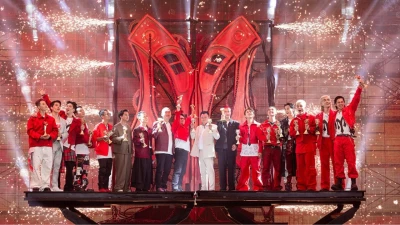
Thi Công Sân Khấu Gameshow Anh Trai Vượt Ngàn Chông Gai Với Giải Pháp Chuyên Nghiệp
Đội ngũ kỹ sư MPX đã hoàn thành xuất sắc dự án thi công sân khấu cho gameshow truyền hình Anh Trai Vượt Ngàn Chông Gai . Chúng tôi mang đến hệ thống sàn mô-đun chịu lực cao và tích hợp hiệu ứng ánh sáng chuẩn studio. Dự án đáp ứng các tiêu chuẩn khắt khe về độ an toàn cho chuỗi thử thách vận động liên tục của nghệ sĩ.
View Details →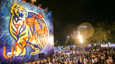
Dự Án Thi Công Bức Tường Tiger Xuyên Việt Với Hệ Kết Cấu Thép Mô-Đun
Năm 2018, đội ngũ kỹ sư MPX vinh dự đảm nhận vai trò nhà thầu thi công toàn bộ hệ thống Bức Tường Tiger. Chiến dịch mang thông điệp "Đánh Thức Bản Lĩnh" đã ghi dấu ấn mạnh mẽ tại ba thành phố trọng điểm: TP.HCM, Đà Nẵng và Hà Nội. Chúng tôi mang đến hệ thống kết cấu thép vững chắc kết hợp cùng kỹ thuật ánh sáng hiện đại tạo nên không gian thương hiệu đẳng cấp.
View Details →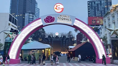
MPX Thi Công Giải Vô Địch Teqball Thế Giới 2024 Tại TP.HCM
Đội ngũ kỹ sư MPX đã hoàn thành xuất sắc dự án thi công toàn diện cho Giải Vô Địch Teqball Thế Giới 2024 tại khu vực TP.HCM. Chúng tôi trực tiếp cung cấp giải pháp kết cấu chịu lực an toàn cho mặt bằng thi đấu, khán đài và hệ thống thiết bị sự kiện đồng bộ. Kết quả mang lại một không gian thể thao đẳng cấp, đáp ứng trọn vẹn tiêu chuẩn phát sóng toàn cầu.
View Details →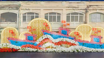
Dự Án Thi Công Hội Hoa Xuân Trên Bến Dưới Thuyền 2025 Tại Bến Bình Đông
Đội ngũ kỹ sư MPX vinh dự đảm nhận hạng mục kiến trúc trang trí tại Hội Hoa Xuân trên bến Bình Đông năm 2025. Chúng tôi đã trực tiếp thiết kế và lắp đặt hệ thống cảnh quan mang đậm bản sắc văn hóa miền sông nước. Toàn bộ công trình đáp ứng tiêu chuẩn an toàn kỹ thuật khắt khe của cơ quan quản lý địa phương tại Thành phố Hồ Chí Minh.
View Details →

NEED CONSULTATION FOR YOUR STAGE SOLUTION?
The MPX team is always ready to provide solution consultation, recommend suitable equipment, and offer technical support for your project.